
Designing Parts for Waterjet Cutting: Kerf, Taper, and Minimum Feature Size
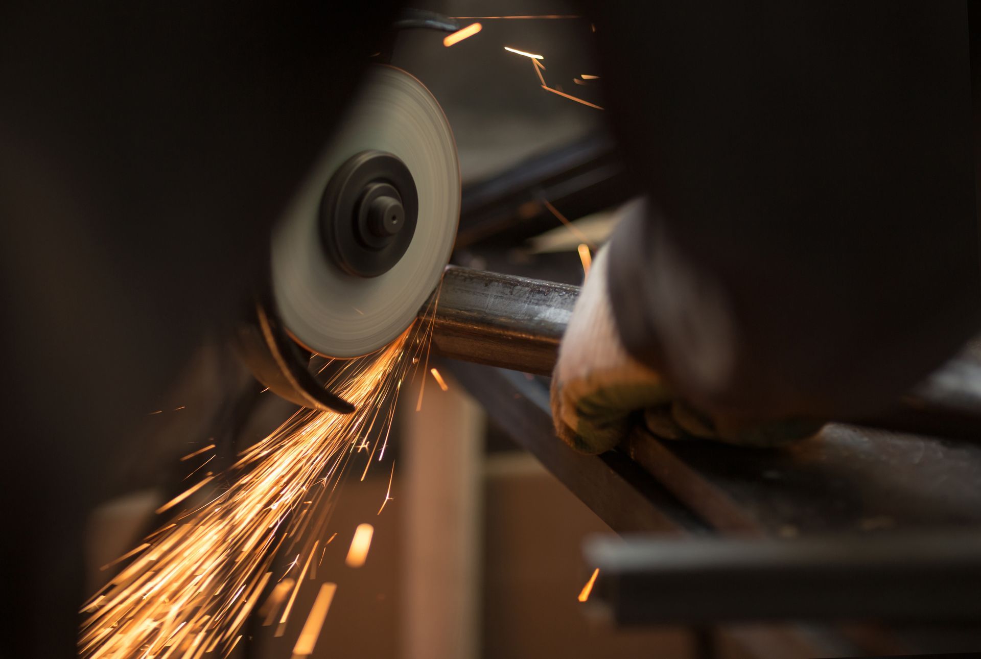
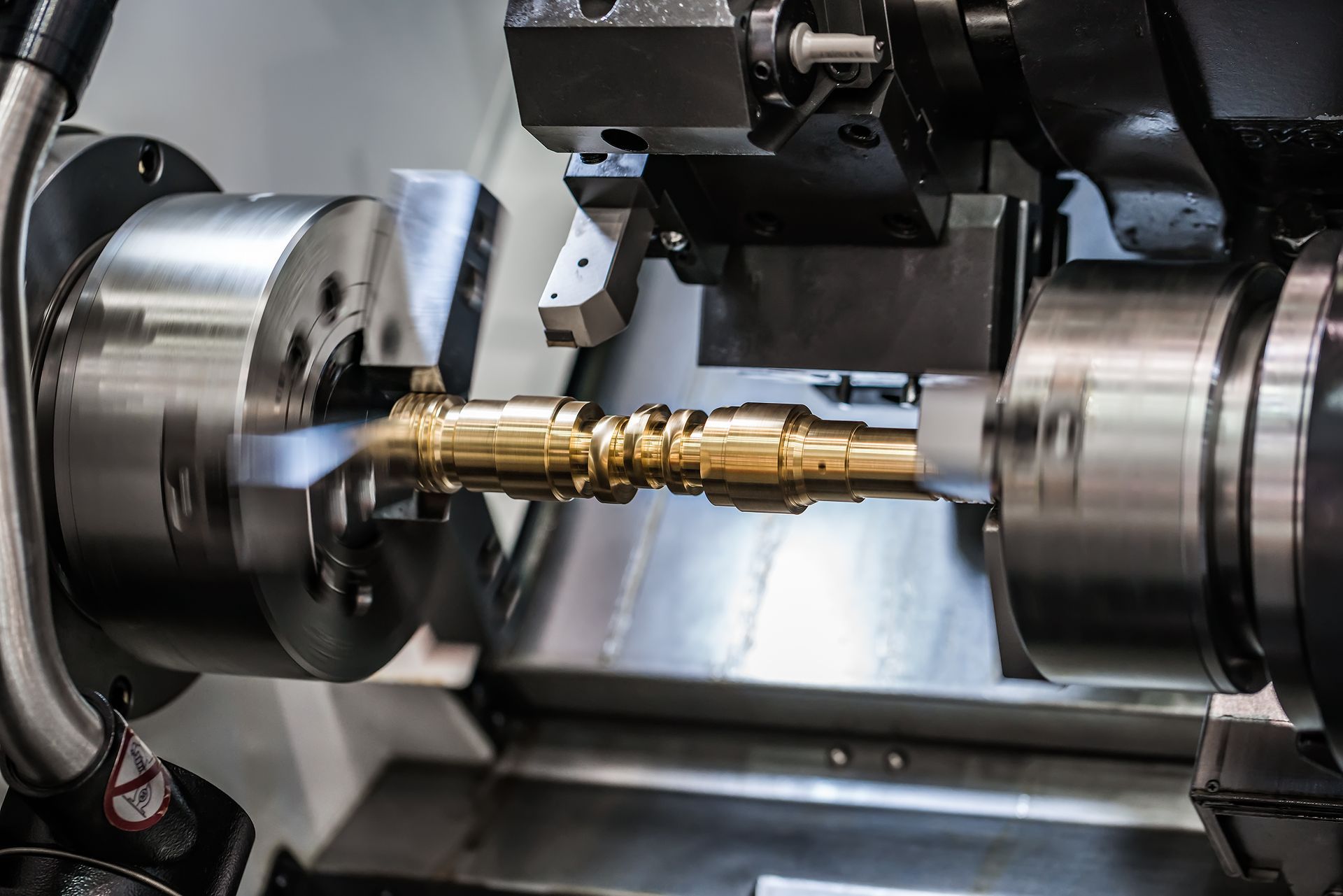
Waterjet cutting continues to be one of the most versatile and precise fabrication methods available today particularly for stainless steel, aluminum, and other metals that demand tight tolerances and minimal heat distortion. For engineers and fabricators, however, success with waterjet doesn’t just depend on the machine. It starts with smart part design.
Understanding how kerf width, taper, and feature size interact with waterjet processes is essential to achieving accurate results and reducing scrap or post-processing. At Action Stainless, we supply waterjet-ready stainless and aluminum sheet, plate, and bar cut in-house or prepped for your shop’s own equipment with dimensional control that supports today’s most demanding tolerances.
Whether you’re producing brackets, components, decorative panels, or OEM parts, this guide walks through the design considerations that matter most when preparing parts for waterjet cutting.
The Basics of Waterjet Cutting and Why Design Matters
Waterjet cutting uses high-pressure water (often 50,000–90,000 PSI), sometimes mixed with abrasive garnet, to erode through material in a focused stream. It is a cold-cutting process, meaning there’s no heat-affected zone (HAZ), making it ideal for materials like:
- Stainless steel (including 304, 316, 2205 duplex, 17-4 PH)
- Aluminum (5052, 6061, and others)
- Nickel alloys and titanium
- Plastics and composites
Despite its flexibility, waterjet cutting has its own set of limitations especially when it comes to
kerf width, part geometry, edge taper, and minimum cuttable feature sizes. Designing with these constraints in mind helps avoid accuracy issues, warped parts, or unwanted bevels.
What Is Kerf in Waterjet Cutting?
Kerf refers to the width of the material removed by the cutting stream. In waterjet cutting, kerf width is influenced by:
- Nozzle size
- Abrasive flow rate
- Water pressure
- Standoff height
- Cutting speed
- Material hardness and thickness
In most setups, kerf typically ranges from 0.030" to 0.045", depending on the machine and application. However, this cut width must be factored into your CAD drawings and design tolerances. Parts that rely on tight internal fits such as tabs, slots, or interlocking pieces must accommodate for kerf loss or include compensation paths in tool settings.
If not considered, parts may come out undersized, holes may shrink, and critical mating features could misalign.
Managing Kerf Compensation in Design Files
To ensure part dimensions match your intended specifications, you can apply kerf compensation in one of two ways:
- Offset the toolpath in your CAM software: This is the most common method. The CNC controller compensates for kerf automatically during programming.
- Adjust your CAD dimensions manually: For shops without automatic toolpath compensation, designers must add kerf width to outside contours and subtract it from inside contours.
At Action Stainless, when we cut parts in-house using customer-supplied DXF or CAD files, we confirm whether kerf offsets are included or should be handled by our programming team. This ensures your cut parts arrive within tolerance whether they’re destined for welding, forming, or immediate assembly.
What Is Taper in Waterjet Cutting?
Even with precise cutting, waterjets naturally produce a slight taper in the cut edge, especially on thicker material. Taper occurs because the cutting stream narrows as it penetrates deeper, removing more material at the top of the cut than the bottom.
There are two types of taper:
- V-Taper: Narrower at the bottom; common with standard cuts.
- Reverse Taper: Wider at the bottom; less common and typically caused by deflection or excessive dwell.
Taper size is influenced by:
- Material thickness
- Cutting speed
- Abrasive consistency
- Nozzle wear and maintenance
As a general rule, taper is more pronounced in cuts over 0.375" thick, but modern machines with dynamic heads can correct this, maintaining straight edges by tilting the nozzle during cutting. However, not all waterjet setups include dynamic compensation, and thin materials (< 0.125") may not need it at all.
Designing with Taper in Mind
To reduce taper-related issues in your designs:
- Avoid relying on square edges for load-bearing or seal-critical applications if the taper isn’t corrected.
- Specify tolerances that accommodate slight beveling, especially in thick stainless or aluminum.
- Communicate with your cutting partner like Action Stainless about whether taper compensation is available and what material thickness thresholds apply.
If your part requires laser-precision perpendicularity or zero beveling, we may recommend an alternate cut method, or using thinner material paired with tight jet stabilization controls.
What’s the Minimum Feature Size for Waterjet Cutting?
Waterjets excel at intricate cuts, but there are physical limits to the size of features that can be accurately produced. Trying to cut too-small holes, slots, or tabs can lead to distortion, overcutting, or complete part failure.
Minimum feature size depends on:
- Kerf width
- Material type and thickness
- Nozzle wear and water pressure
- Cutting speed and nozzle stability
As a baseline, don’t design features smaller than 1.5x your kerf width. For a 0.040" kerf, the smallest reliable hole or web should be no smaller than 0.060" - 0.065". For thicker plate, that minimum may increase.
If your part requires tiny text, logos, or precision cutouts, communicate that up front, and Action Stainless can guide your design around what’s physically achievable based on your material choice.
Material Thickness vs. Design Complexity
Thicker stainless or aluminum sheet (e.g., 3/8" or 1/2") limits the tightness of inside corners, radii, and slot geometry. The wider the material, the more taper and kerf distortion can affect delicate features.
For complex parts:
- Use radiused internal corners to reduce stress and edge distortion
- Avoid very sharp points or narrow tabs that may warp during cutting
- Use uniform thickness to ensure cutting parameters remain constant throughout the job
At Action Stainless, we’ll review your design if needed before cutting, and we always cut from flat, certified sheet and plate to prevent deviations caused by camber, warp, or surface imperfections.
Design Tips for Better Waterjet Results
To get the best results when using waterjet on stainless or aluminum, keep these general design principles in mind:
- Incorporate generous lead-ins and lead-outs in the toolpath for clean pierces
- Avoid placing small features too close together
- Use larger radii instead of sharp internal corners
- Consider clamping and fixturing access during cutting
- Plan for edge taper and minimum feature size in critical areas
If you’re unsure how to adjust your design, Action Stainless offers assistance with pre-cut file review and consultation especially for high-precision jobs or new material combinations.
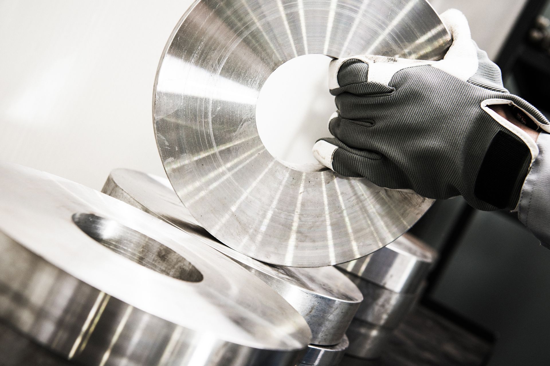
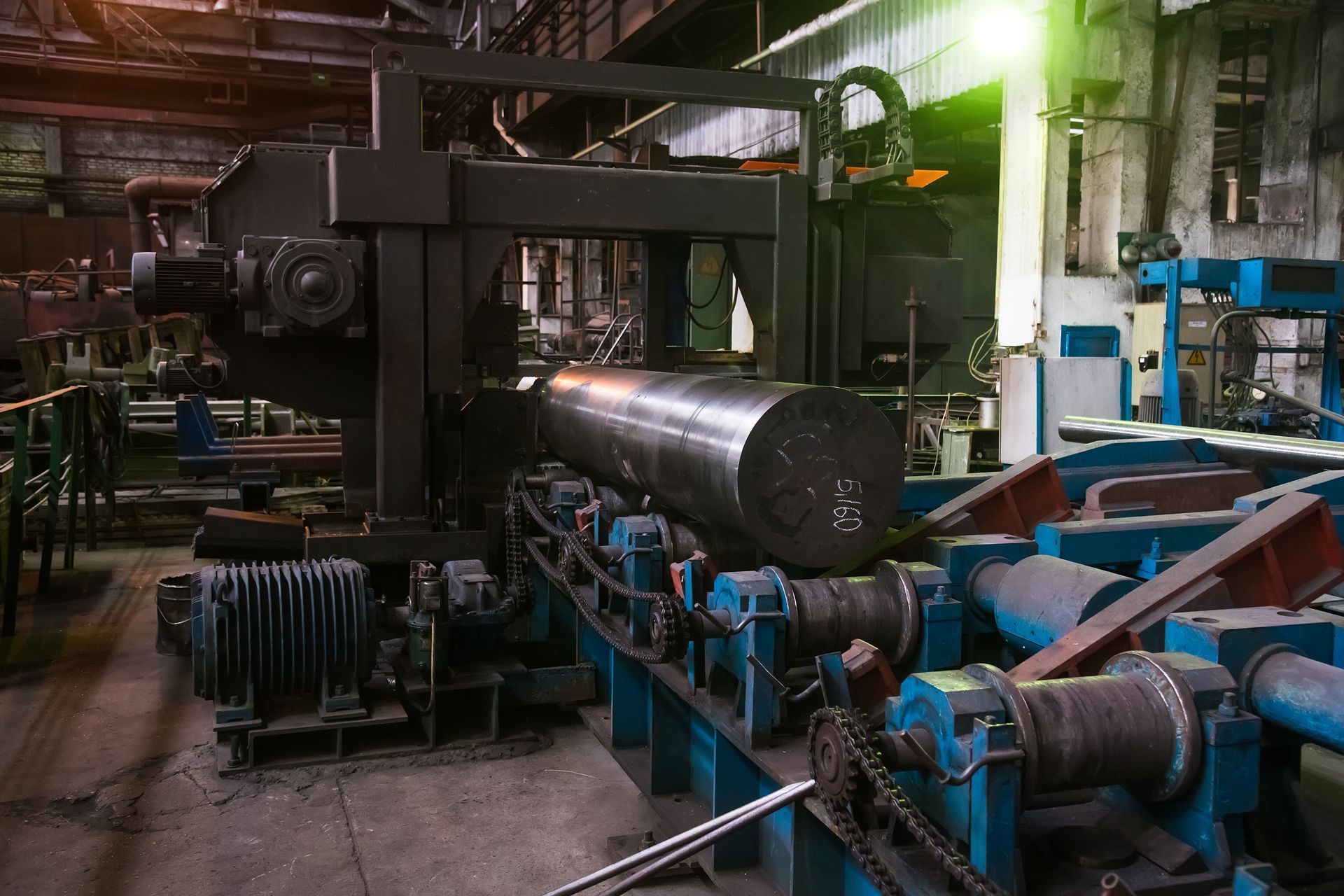
In-House Waterjet Material Preparation at Action Stainles
We stock and process stainless and aluminum grades that are ideal for waterjet cutting:
- 304 / 304L
- 316 / 316L
- 5052, 6061
- 2205 Duplex Stainless
- 17-4 PH stainless (for high-strength components)
We also offer:
- Shearing and flattening of material before cutting
- Protective film application to avoid surface damage during cutting
- Custom packaging to prevent edge damage in transit
- Mill Test Reports (MTRs) for traceability and compliance
By prepping all waterjet-ready material in-house, we help our customers reduce scrap, avoid rework, and ensure cut-ready deliveries arrive on time.
Why Action Stainless Customers Choose Waterjet-Ready Material
For fabricators using in-house waterjet systems or working with third-party cutting vendors, buying prepped and certified stainless or aluminum eliminates several steps. Our customers rely on us for:
- Consistent thickness tolerances
- Flat, defect-free sheet or plate
- Saw-cut bar stock for machining or fixturing
- Exact dimension blanks for job shop CNC work
Whether you're cutting architectural panels or industrial flanges,
we support your process by delivering the right material, in the right condition, every time.
Conclusion: Better Waterjet Results Start with Smart Design
Designing for waterjet cutting means more than just exporting a DXF file. To achieve tight tolerances, clean edges, and defect-free parts, engineers must understand and account for kerf width, taper effects, and feature size limits. A great design won’t succeed if it ignores the physics of the cut.
At Action Stainless, we work closely with fabricators, OEMs, and job shops to ensure your stainless or aluminum arrives cut-ready, laser-flat, and certified so your design becomes reality without delay or error.
Looking for stainless sheet or aluminum plate prepped for waterjet? Contact our team today and we’ll help match your design goals with the best material and prep options.